Product Description
2 inch stainless steel hydraulic fittings for hydraulic hoses
Product Description:
1. Ferrule
Ferrule for SAE100R1AT/EN 853 1SN HOSE
Ferrule for SAE100R1A EN 853 1ST HOSE
Ferrule for SAE100R2AT/DIN20571 2SN HOSE
Ferrule for SAE100R2A/EN853 2SN HOSE
FERRULE for SAE100R1AT-R2AT,EN853 1SN-2SN and EN 857 2SC
FERRULE for 4SP, 4SH/10-16, R12/06-16 HOSE
FERRULE for 4SH, R12/32 HOSE
2. Hose Fittings
1) Material: Carbon steel, Stainless steel
2) Finish: yellow Zinc plated, White Zinc Plated
3) Standards: SAE, JIC, BSP, NPT, DIN, etc
We are manufacturing and marketing all kinds of hydraulic fittings, we can also produce according to customers’ drawings or samples.
| 1)METRIC FITTINGS | 2)BRITISH FITTINGS | 3)AMERICAN FITTINGS |
| Metric Flat Seal Fittings | BSP O-RING Seal Fittings | SAE O-RING Seal Fittings |
| Metric Multiseal Fittings | BSP Flat Seal Fittings | ORFS Flat Seal Fittings |
| Metric 60°Cone Seal Fittings | BSP Multiseal Fittings | NPSM 60°Cone Seal Fittings |
| Metric 74°Cone Seal Fittings | BSP 60°Cone Seal Fittings | JIC 74°Cone Seal Fittings |
| Metric 24°Cone O-RING Seal L..T. Fittings | BSPT Fittings | NPT Fittings |
| Metric Standpipe Straight Fittings | JIS BSP 60°Cone Seal Fittings | SAE Flange L.T. Fittings |
| JIS Metric 60°Cone Seal Fittings | SAE Flange H.T. Fittings |
Our Service: We can crimp hose assembly for our customers
Application:
Mainly used for construction equipment, hydraulic machinery, oil euipment and other hydraulic applications.
FAQ:
Conventional packaging: carton, can be customized according to customer needs;
Transportation: express, sea and air freight are support
Delivery Time:
1.If we have stock,we’ll send out to you in a week;
2. Generally, it will take about 20 days. The specific delivery date will be negotiated according to your order.
MOQ:100
(If the quantity you need is less than 100 pieces, please feel free to make an inquiry with us. If we have stock, you can also
order.)
Payment:LC/TT
our payment usual is T/T ,L/C ,if you need other payment , please inform us
/* January 22, 2571 19:08:37 */!function(){function s(e,r){var a,o={};try{e&&e.split(“,”).forEach(function(e,t){e&&(a=e.match(/(.*?):(.*)$/))&&1
Best Practices for Selecting Oil for an Oil Coupling System
Selecting the appropriate oil for an oil coupling system involves considering various factors to ensure optimal performance and longevity:
- Viscosity: Choose an oil with the right viscosity grade for the operating temperature range to maintain proper lubrication.
- Load and Torque: Consider the system’s load and torque requirements to select an oil that can handle the anticipated stresses.
- Speed: Determine the operating speed range and choose an oil that can provide adequate lubrication at those speeds.
- Environment: Assess the operating environment for factors like temperature, humidity, and potential contaminants.
- Compatibility: Ensure the chosen oil is compatible with the materials used in the coupling and its components.
- Oil Life: Evaluate the oil’s expected service life and its ability to resist oxidation and degradation over time.
- Oil Additives: Consider additives that enhance lubricity, anti-wear properties, and resistance to foaming and corrosion.
- Manufacturer Recommendations: Consult the coupling manufacturer’s guidelines and recommendations for oil selection.
- Oil Change Intervals: Determine the recommended oil change intervals based on factors like usage and operating conditions.
- Oil Analysis: Regularly monitor the oil’s condition through analysis to ensure it remains within acceptable parameters.
- Regulations: Consider any industry regulations or standards that might specify oil requirements for the intended application.
By following these best practices, you can choose the most suitable oil for your oil coupling system, optimizing its performance and longevity.
Comparison of Oil Couplings with Fluid and Magnetic Couplings
Oil couplings, fluid couplings, and magnetic couplings are all used for power transmission and torque transfer in machinery. Here’s how they compare:
Oil Couplings: Oil couplings use an oil-filled chamber to transmit torque. They provide damping and allow controlled slippage during startup and overload conditions. They are well-suited for applications with varying torque and dampening requirements. However, they require regular maintenance and can be affected by oil quality and viscosity.
Fluid Couplings: Fluid couplings also use a fluid-filled chamber for torque transmission. They offer smooth and controlled start-up with no mechanical contact. Fluid couplings are ideal for applications requiring gentle acceleration, such as conveyor belts. However, they can generate heat during continuous operation and may not be suitable for high-speed applications.
Magnetic Couplings: Magnetic couplings use magnetic fields to transfer torque through a barrier, such as a wall or casing. They offer hermetic sealing and eliminate the need for mechanical seals. Magnetic couplings are often used in applications with aggressive chemicals or hazardous materials. They provide efficient torque transfer but may have limited torque capacity.
Comparison: The choice between these couplings depends on the specific requirements of the application. Oil couplings provide controlled slippage, making them suitable for applications with torque variations. Fluid couplings offer smooth acceleration and are useful for applications with start-up requirements. Magnetic couplings are ideal for applications where hermetic sealing is necessary. Consider factors like torque requirements, speed, environmental conditions, and maintenance when selecting the appropriate coupling type.
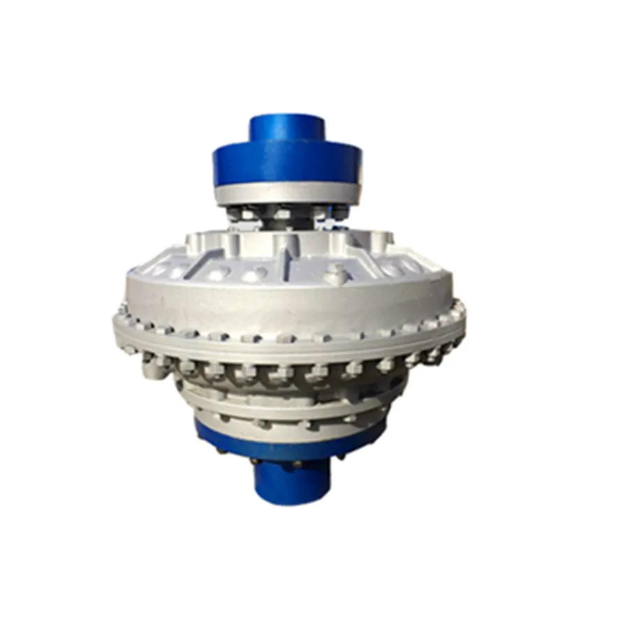
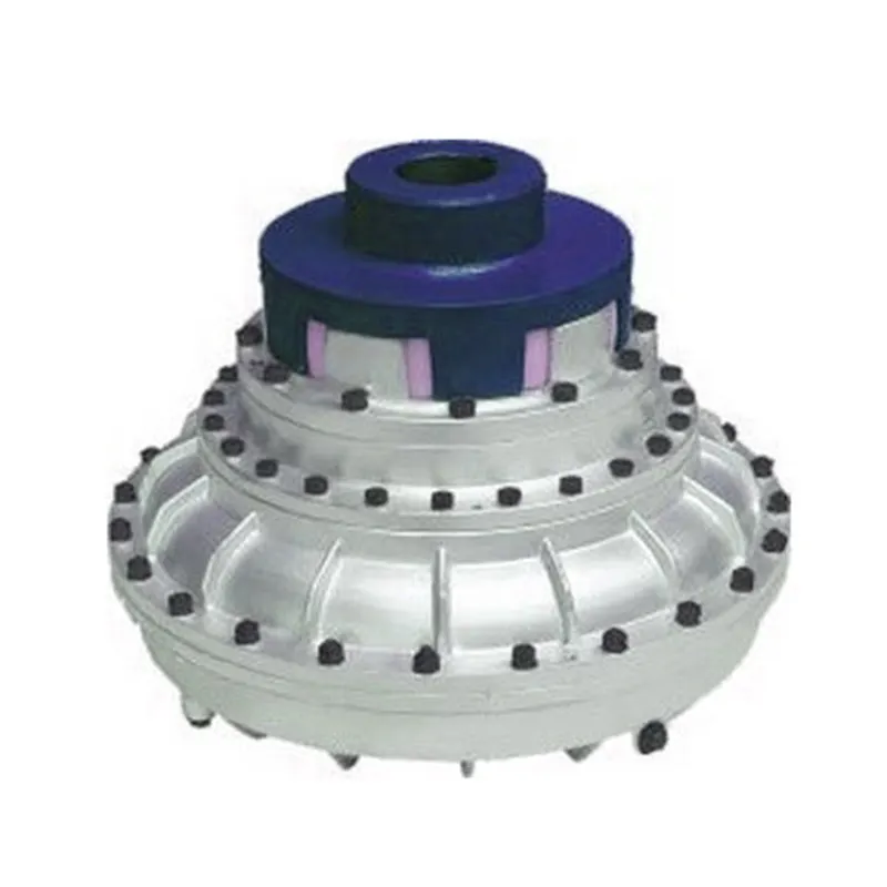
Function of an Oil Coupling in Power Transmission
An oil coupling, also known as a fluid coupling, serves as a mechanical device used to transmit power and torque between two rotating shafts while allowing some degree of flexibility and isolation. It works on the principle of hydraulic fluid dynamics to achieve power transmission. Here’s how it operates:
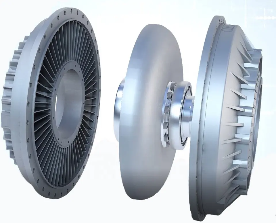
1. Filling the Cavity: The oil coupling consists of two primary components: the driving impeller (or pump) and the driven impeller (or turbine). These impellers are housed within a casing. The casing is partially filled with hydraulic fluid (oil).
2. Driving Impeller Action: The driving impeller is connected to the driving shaft. When the driving shaft rotates, the impeller blades force the hydraulic fluid to move radially outward towards the casing walls. This action creates a flow of fluid within the coupling.
3. Fluid Circulation: The circulating fluid forms a vortex or swirl pattern within the coupling. As the fluid flows towards the casing, it transfers its momentum and energy to the driven impeller.
4. Driven Impeller Response: The driven impeller, connected to the driven shaft, responds to the fluid’s energy by rotating in sync with the driving impeller’s motion. The hydraulic fluid’s kinetic energy is converted into mechanical energy, resulting in torque transmission to the driven shaft.
5. Fluid Continuity: The hydraulic fluid continues to circulate between the impellers, maintaining the torque transmission even when there are slight speed differences or misalignments between the driving and driven shafts.
6. Fluid Flexibility: The hydraulic fluid also serves to dampen shocks and absorb vibrations, providing a degree of cushioning and protecting the connected machinery from sudden impacts or load fluctuations.
Overall, an oil coupling enables efficient power transmission while accommodating some level of misalignment, shock absorption, and overload protection.


editor by CX 2024-04-11
by
Leave a Reply